555 timer ic 555 circuit timer diagram does ne555 pinout work block mode eleccircuit frequency oscillator using draw running building when use astable Relay circuit arduino hackster
Remote Control Light Bulb using a Relay - Hackster.io
Remote control light circuit diagram 555 timer circuit monostable electronics circuits pulse diagram multivibrator ws tutorials sinking sourcing bistable tutorial led trigger time projects output 555 timer schematic : 555 timer astable circuit electrical engineering
Remote light switch control circuit simple make
555 timer internal schematic : 555 timer circuits555 timer ic working Abfahren ausgraben stadion flip flop circuit using 555 tourist parade555 timer circuits blinking component.
Remote control light bulb using a relay4017 chaser timer capacitor electrosome Circuit diagram control remote light switch lamp timer 555 using circuits remot controlled555 timer ic.

Traffic light circuit using 555 timer
Remote control light circuit diagram using 555 timer555 timer ic pin diagram How does ne555 timer circuit workAdjustable timer circuit using 555.
Automatic light using 555 timerHow to make a remote control light circuit, simple remote switch Timer ne555 eleccircuit pinout datasheetRemote control light circuit diagram.

Tutorial for beginners : march 2016
Simple timer circuit using ic 555, 56% offHow does ne555 timer circuit work Timer ic block diagram working pin out configuration data sheet[diagram] 555 timer chip diagram.
How does ne555 timer circuit work555 timer tutorial 555 timer circuit diagramDiy, ao, 1x cégré ne555 ne555p, pi, t €0.99 holidayhimalayas.com.

555 timer tutorial: how it works and useful example circuits
555 timer schematic symbolAutomatic light using 555 timer Circuit diagram for remote control light.
.


Remote Control Light Bulb using a Relay - Hackster.io

abfahren ausgraben Stadion flip flop circuit using 555 Tourist Parade

555 Timer Internal Schematic : 555 Timer Circuits - kathleen-stander
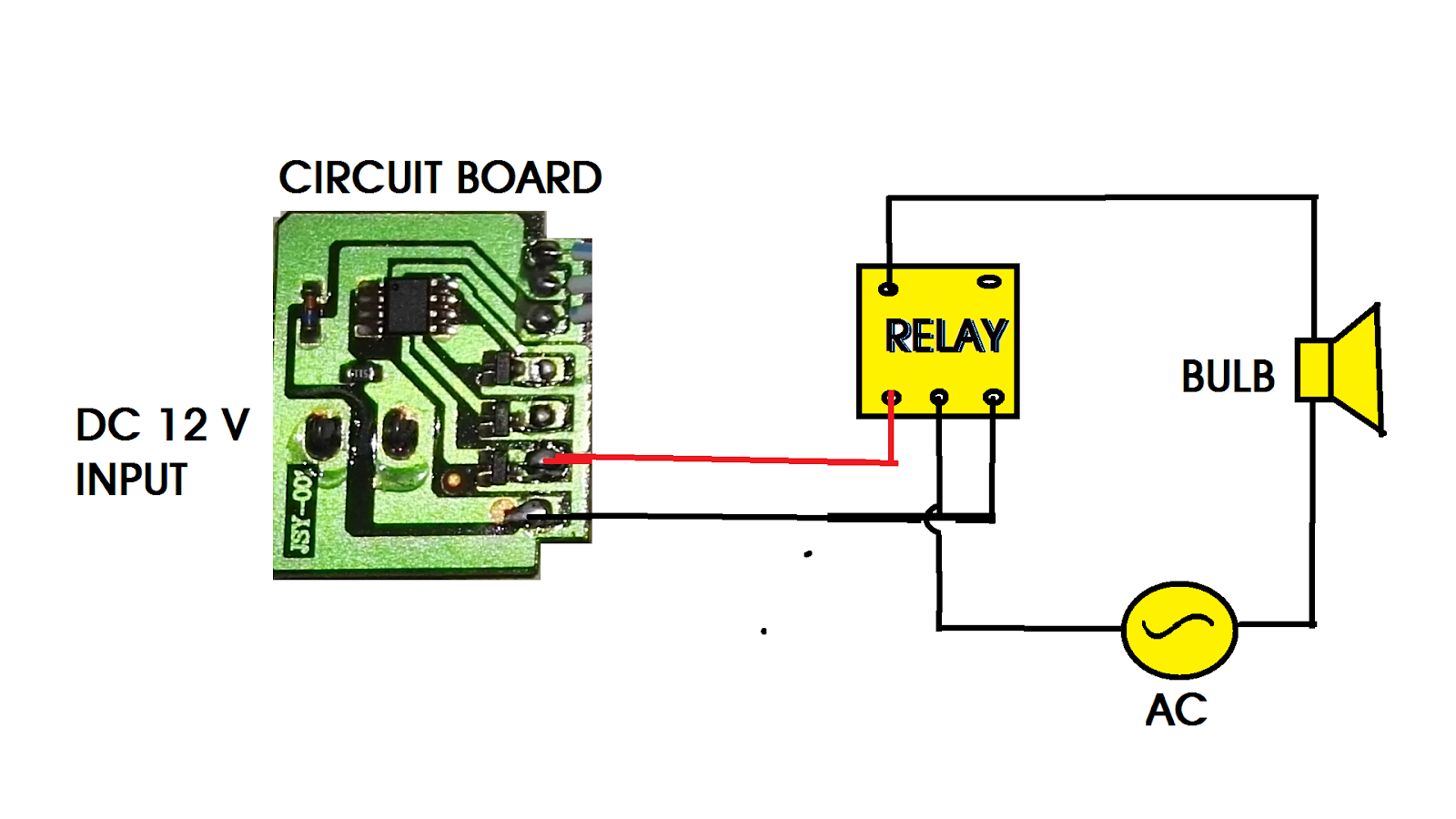
Circuit Diagram for Remote Control Light
![[DIAGRAM] 555 Timer Chip Diagram - MYDIAGRAM.ONLINE](https://i2.wp.com/circuitspedia.com/wp-content/uploads/2017/12/internal-2.jpg)
[DIAGRAM] 555 Timer Chip Diagram - MYDIAGRAM.ONLINE

How does NE555 timer circuit work | Datasheet | Pinout | ElecCircuit.com

Traffic Light Circuit using 555 Timer
Timer Ic Block Diagram Working Pin Out Configuration Data Sheet | My
